目录
Abstract
The advantages of the geometric specification of a product are here illustrated by converting a traditional 2D coordinate tolerancing drawing using the geometrical tolerance method. The new language of symbols permits the functional requirements of the products to be fully expressed in technical documentation. Moreover the dimensioning of a workpiece according to the geometrical tolerance method can reduce the ambiguity in the indications and in the interpretation of the dimensional and geometrical requirements of the products in order to achieve not only unambiguous communication between the design, production and quality control entities, but also with the clients and suppliers of the outsourced processes.
1 Conversion from Traditional 2D Coordinate Tolerancing
Let us now consider the dimensioning of the previous workpiece according to the geometrical tolerance method (Fig. 3.1), utilising symbols and codes that will be dealt with in more detail later on.
In order to apply thismethod, some simple principles should be taken into account:
- Two Cartesian reference systems should be set up (through three orthogonal planes indicated as A, B, C and an axis D in Fig. 3.2) with respect to which all the geometrical components should be located in a univocal manner.
- The zone and the tolerance value should be defined for each feature (Fig. 3.3). The real features of the part should fall within the boundary of their theoretical location, that is, the one they have in the ideal component.
- The tolerance zones are located and orientated with respect to the reference system: for example, the cylindrical tolerance zone of the central 20 mm hole is oriented perpendicular to datum plane A and located, with Theoretically Exact Dimensions (TED), with reference to datum planes B and C.
- Plus or minus tolerancing is only used to define the dimensions of a feature of size1 (the holes in this case).
- The tolerance zone is increased if a circled M is indicated inside the tolerance indicator of the location tolerance. This means that this tolerance has been foreseen to ensure functioning when the hole is under maximum material conditions (that is, with the minimum diameter) and it is accepted that, if the hole is produced with a larger diameter, mating will also be possible, even with a larger location error (Maximum Material Requirement).
1 A feature of size (FOS) is a set of two opposite elements associated with a size dimension.

Fig. 3.1 The dimensioning of a workpiece through the geometrical tolerancemethod: the tolerance zones become clear and univocal and the tolerance zones on profiles are equivalent in amplitude to those obtained by means of traditional dimensioning, but an undesired accumulation of errors is avoided, and the datum sequence is reported immediately and in a simple manner for the inspection
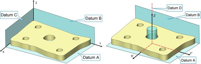
Fig. 3.2 In order to apply the functional dimensioning principles, two Cartesian coordinate systems should be set up, with respect to which all the geometric features of the component will be located
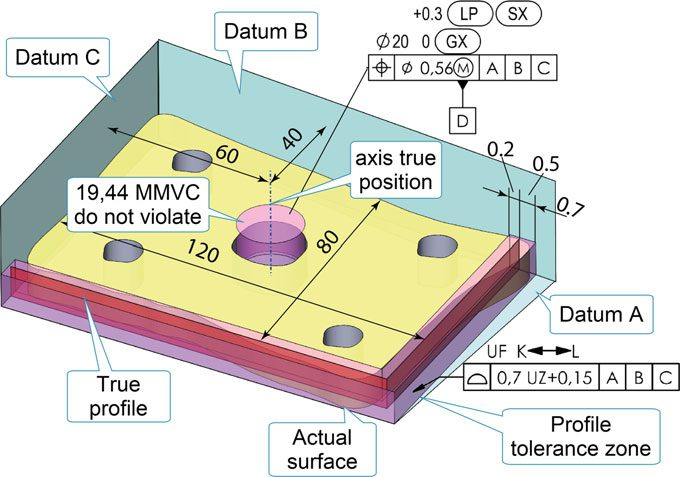
Fig. 3.3 The zone and tolerance value of each feature should be defined. The real features of the part should fall within the boundary of their theoretical location, that is, within the location they have in the ideal workpiece
The feature of size concept ISO definition: according to ISO 17450/1 a feature of size with a linear size is a geometrical feature that has one or more intrinsic characteristics, only one of which may be considered as a variable parameter. A feature of size can be a sphere, a circle, two straight lines, two parallel opposite planes or a cylinder. A single cylindrical hole or shaft is a linear size feature. Its linear size refers to its diameter. An axis, median plane or centrepoint can be derived from a feature of size. ASME definition: a regular feature of size is a one cylindrical surface, a spherical surface, a circular element, or a set of two opposite parallel line elements or opposite parallel surfaces associated with a single directly toleranced dimension.
A feature of size:
1. is characterized by opposite points on a surface;
2. an axis, a median plane or a centrepoint may be derived;
3. is associated with a size or a mating dimension.
Which features in Fig. 3.4 are features of size?
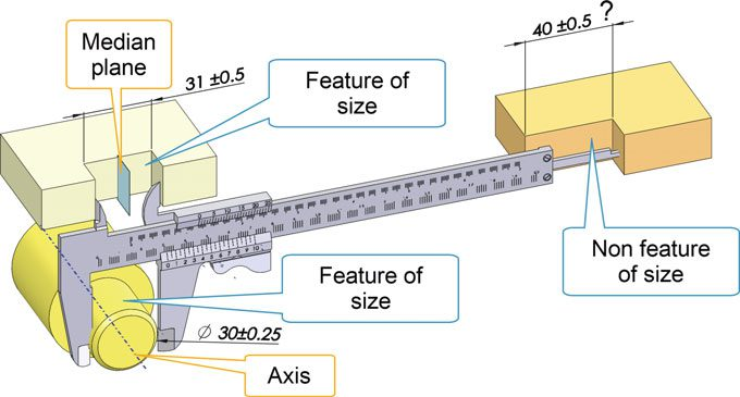
Fig. 3.4 The characteristics of a feature of size
2 Advantages of Geometrical Product Specification
Several advantages can be achieved from the application of this type of dimension:
- a cross section of a cylindrical tolerance zone circumscribed about a square tolerance zone, like the one shown in Fig. 3.5, has 57% more area than the square zone, in which a point of the extracted median line of the hole may lie. It can in fact be noted in Fig. 3.5 that, for the same maximum amplitude of admissible tolerance, that is, 0.56 (as shown in Fig. 1.6), even those features that fall outside the tolerance range would be acceptable, according to what is indicated in Fig. 1.6, because they have a point of extracted median line located inside the round segments;
- the holes are located with respect to the three-plane datum system, and this means that, for the control, the workpiece should first be placed in contact with datum A, and then in contact with datum B and finally fixed with datum C (Fig. 3.6); in this way, the control is univocal and repeatable, even when carried out in different periods of time and by different workers;
- no problem of tolerance accumulation arises, as all the location dimensions refer to theoretically exact dimensions;
- in certain cases, by applying the MMR2 requirement, some tolerances can be doubled; in fact, the location tolerance of a hole (0.56 mm) becomes 0.86 mm when the hole is produced under the minimum material condition (20.3 mm);
- the dimensioning and tolerancing of each feature should be complete and clearly defined, so that the form, orientation, location, and where applicable, the size of each feature on a part are fully defined on a part. It is possible to directly locate the dimensioning on a 3D CAD model, as shown in Fig. 3.7, where the theoretically exact dimensions are those of the native geometry of the model.
2See Sect. 5.1.1.
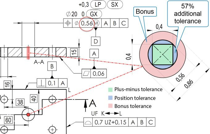
Fig. 3.5 The location tolerance of the extracted median line of the hole defines a cylindrical zone with an increase of 57%, compared to the coordinate dimensioning tolerance shown in Fig. 1.3. A further bonus of 0.3 mm is obtained when the hole is produced under the minimum material conditions (as the tolerance is indicated with the maximum material requirement symbol)
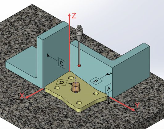
Fig. 3.6 The holes are located with respect to the three-plane datum system. This means that, for the control, the workpiece is first placed with reference to datum A, then moved against datum B and finally fixed with datum C; in this way, the control is univocal and repeatable, even though carried out in different periods and by different workers
In short, more reduced and poorer quality functionality and performances of products are obtained with the traditional design (that is,with the coordinate dimensioning system), and the correct assembly of the components is not always guaranteed. Moreover, ambiguous and misunderstanding indications are given for the manufacturing of the parts, and their control is often random.
Table 3.1 summarises the differences between the two dimensioning systems. Companies, in the actual production context, should adopt advanced specification and geometrical verification methodologies, based on the most recent developments of the international ISO and ASME standards, for their products in order to:
- Fully express the functional requirements of the products in the technical documentation;
- Reduce ambiguity in the indications and in the interpretation of the dimensional and geometrical requirements of the products in order to achieve unambiguous communication between the design, production and quality control entities, but also with the clients and suppliers of the outsourced processes.
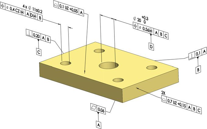
Fig. 3.7 Dimensioning of an equivalent 3D solid model to that shown in Fig. 3.1. The theoretically exact dimensions are those of the native geometry of the model
Table 3.1 Comparison between plus-minus tolerancing and GD&T tolerancing
| Plus-minus tolerancing | GPS tolerancing | |
| Inspection method | • Multiple inspections may produce different results • Good parts may be scrapped |
• The datum system communicates the right set up for inspection • Clear instruction for inspection |
| Tolerance zone | • The tolerance zone is fixed in size • Functional parts may be scrapped |
• The use of modifiers allows the tolerance zone to be increased • Disputes over part acceptance are eliminated |
| Tolerance zone shape | • Square or rectangular tolerance zone for hole locations | • A diameter symbol allows round tolerance zones to be obtained with +57% more tolerance |
Ultimately, GPS (or GD&T) is a symbolic language that can be used to search for, refine and encode the function of each feature of a part in the design phase, with the objective—through the decoding process—of guaranteeing assembly and functionality, specifying the manufacturing objectives, reducing the production costs and of transforming the control into a real scientific and reliable process.