目录
Abstract
The technical product documentation that is currently drawn up in many companies is unfortunately still ambiguous and contains many errors, such as erroneous datums, imprecise or missing distances, as well as incongruent and difficult to check tolerances. For about 150 years, a tolerancing approach called “coordinate tolerancing” was the predominant tolerancing system used on engineering drawings. This methodology in fact no longer results to be the most suitable for the requirements of the modern global productive realty, in which companies, for both strategic and market reasons, frequently resort to suppliers and producers located in different countries, and it is therefore necessary to make use of communication means in which the transfer of information is both univocal and rigorous. GD&T or GPS is a symbolic language that is used to specify the limits of imperfection that can be tolerated in order to guarantee a correct assembly, as well as the univocal and repeatable functionality and control of the parts that have to be produced.
1 The Shortcoming of Traditional Coordinate Tolerancing
Geometric Dimensioning and Tolerancing (GD&T) or Geometric Product Specification (GPS) is a fundamental design tool that is used to clearly and unambiguously define the allowable limits of imperfection of as-produced parts, with the aim of guaranteeing assembly and functionality.
GD&T, or GPS, is a language that is made up of symbolswhich can be used to accurately control tolerances, but it also allows the maximum manufacturing flexibility and control of the costs to be achieved.
Real surfaces can in fact differ, to various extents, from the exact geometric form foreseen during the design phase, both as far as the geometric form is concerned and for the pre-established position with respect to other surfaces assumed as a reference, as a result of various factors (bending of the workpiece and of the tool during the tooling, vibrations of the machine, deformations during hardening, etc.).
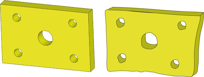
Fig. 1.1 The real surfaces of a constructed part may deviate to various extents from both the geometrically exact form indicated during the design phase and from the pre-established position with respect to surfaces or points assumed as a datum.
The workpiece in Fig. 1.1 is shown with the form errors conveniently enlarged for explanatory purposes, but it can also appear as such for the instruments that perform precise measurements (such as the modern CoordinateMeasuringMachines,CMM).
Another example of form error is illustrated in Fig. 1.2: the sinuous trend of the workpiece or not detected by the measurement gauge, which locally ascertains, section by section, the values of the diameters that fall within the dimensional tolerance limits. However, it would be difficult to insert the workpiece easily into an axially extended hole, because the spatial dimension of the pin would be greater than that foreseen for the tolerance.
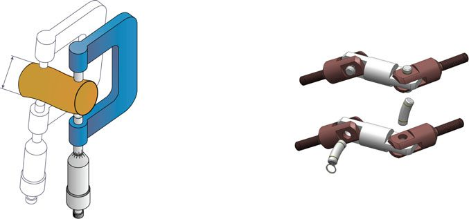
Fig. 1.2 Evaluating the mating conditions by only referring to linear distances leads to the effects of the form being neglected: a smooth f/H shaft-hole mating is in practice forced if the roundness and straightness conditions are not adequate. In fact, the measured maximum dimension, dmax, that conforms to the requested tolerance is less than the Dmax dimension that corresponds to the actual mating dimensions of the pin. Accordingly, it is not possible to fit the hinge pin with the hole because of the error in the straightness of the axis
It is hence necessary to set adequate constraints on the straightness of the axis and on the roundness of the surface. It therefore seems evident that,when establishing the errors that are acceptable in the construction of a part, the form and dimensions should be evaluated in light of the functional requirements. Above all, as the complexity of the designed objects increases, as a result of the numerous technological processes that are now utilised and because of the necessity of guaranteeing quality through careful inspections and verifications, the information that is derived from the project, and therefore from the design of the component that has to be produced, should refer to all the sectors involved as much as possible. The drawings of the workpiece, as requested for the process, should not be ambiguous; the function of the parts, as well as the way of obtaining and controlling them should be completely included and reported.
In short, each feature of a workpiece should be fully defined in terms of dimension, position, orientation and form.
The tolerances, whether geometrical or dimensional, should be essential parts of the design process right from the beginning, and not just an accessory that has to be added only once the design has been completed.
One procedure that can be adopted to satisfy these requirements is the functional dimensioning method, which can be defined as a way of specifying the geometric functionalities and the functional relationships that exist among the form characteristics, in a project or design, in order to obtain the most valid production from both a qualitative and an economic point of view.
The components that have to be controlled and measured can be specificated through this method; in this way, the intentions of the designer are respected, and the manufacturer is able to choose the most appropriate manufacturing procedures.
Computer Aided Design (CAD) tools, which have the purpose of generating, manipulating and reporting the geometry of the parts that have to be produced, are currently used for design purposes, but they are not sufficient on their own to document an industrial product in an effective way.
In order to communicate a precise and rigorous description of a part, not only should the dimensions be indicated in the engineering drawing, but also the admissible error, in terms of size, location, orientation and form.
The term “Geometric Dimensioning and Tolerancing” (GD&T) is often used to characterise a functional design. GD&T is a language made up of symbols that are used to specify the limits of imperfection that can be tolerated in order to guarantee a correct assembly, as well as the univocal and repeatable functionality and control of the parts that have to be produced. Moreover, GD&T is a tool that allows an imperfect geometry to be managed “perfectly”.
The GD&T method was developed and extended during the Second World War by Great Britain and the United States. The first publication concerning a standard, pertaining to the basic concepts of form and position,was published in Great Britain in 1948.1 In 1940, in theUnited States, Chevrolet printed a publication concerning position tolerances, and this was followed, in 1945, by amanual, which was published by the American Military administration, in which symbols were introduced to specify form and position tolerances. Over the following years, the ASA and SAE associations published their own standards, which, in 1966, took on the present forms, although they have periodically been updated (the most recent being in 2018).
About 50 years ago, some companies in Europe began to introduce a few indications relative to admissible geometric errors, and the first mention of this topic appeared in texts on comparative design. In 1969, an ISO recommendation project introduced, at a normative level, the symbols that are used today.However, geometric tolerancewas long considered an option thatwas only to be used in particular and rare occasions, that is, when the dimensional tolerances (which were generally considered suitable if accompanied by a correct execution) were not considered sufficient to define the exact form of a component.
A different approach to tolerances, which couples geometric dimensioning with the functionality of a workpiece, is currently being developed, with the aim of obtaining a shared, clear and comprehensive language for all the production sectors interested in a particular project, and of reporting the finished conditions of the objects that have to be produced in a univocal and faithful way, with the intention of advantaging functionality and reducing costs. As already mentioned, this is not a recent method, but it has still not been fully exploited in many European countries, where the benefits that could be achieved, in practical terms, on the highly competitive markets of today, are often disregarded.
Unfortunately, the technical product documentation that is currently drawn up in many companies is still ambiguous and often contains many errors, such as erroneous datums, imprecise or missing distances, as well as incongruent and difficult to check tolerances. These documents were in fact first conceived considering a series of standards that originated in the technical industrial context of the last century, that is, by referring to the then most widespread measurement instruments, such as gauges and micrometres, in which the measurements were made and expressed as the distance between two points. The most frequently used measurement method was that of coordinate dimensioning, where only the dimensional tolerances (that is, the “plus or minus” system), which could give rise to manufacturing and control ambiguity, were used.
This methodology is in fact no longer results to be themost suitable for the requirements of the modern global productive realty, in which companies, for both strategic and market reasons, frequently resort to suppliers and producers who are located in different countries, and it is therefore necessary to make use of communication means in which the transfer of information is both univocal and rigorous.
2 Traditional Dimensioning Example
Let us consider the drawing in Fig. 1.3 of a plate with 4 holes, for which the assembly with fixed fasteners is demonstrated as an example; the traditional measurement method has been applied to the plate, that is, with the 4 holes being located according to the dimensional tolerances.
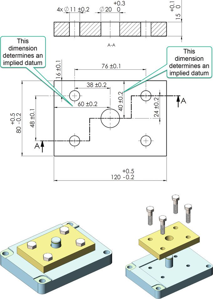
Fig. 1.3 Traditional dimensioning of a plate with 4 holes, for which the functional assembly conditions are shown (coherence of the profiles, perpendicularity of the profile, location of the holes, implied datums)
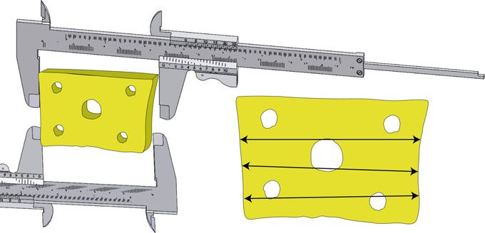
Fig. 1.4 If themeasurement of the dimensions starts from the edges, which are not orientated at 90°, as shown in the drawing, how should the workpiece be arranged exactly to control the dimensional tolerance? Furthermore, as themeasurement is not the individual distance between pairs of opposite points, how are the opposite points determined?
An observation of the thus definedworkpiece leads to the following considerations and questions:
- Are the edges of the workpiece located with respect to the holes or are the holes located with respect to the edges [1]?
- If the distances are considered to originate at the edges, which are not orientated at 90°, as shown in the drawing (Fig. 1.4), howshould theworkpiece be arranged exactly to control the dimensional tolerance? Furthermore, the measurement is not just the individual distance between pairs of opposite points.
- In coordinate tolerancing, since datums are implied and they depend on the interpretation of the metrologists, the placement on the gauging surface may produce different measurement results. Hence it is possible that a good partmay be rejected or a bad partmay be accepted. Furthermore, if the datum sequence is not indicated, the control of the location of the holes can be conducted in different ways (for example, by first checking the position of a hole and from this position then checking the positions of the subsequent holes, or by considering one or two edges as a single datum for all the holes, see Fig. 1.5): such a control is therefore neither univocal nor repeatable.
- The cross-sectional area of the tolerance zone for the position control of the hole axis is square, while the form of the hole is round; therefore, the tolerance area does not mirror the form of the hole that it should protect. Moreover, starting from the theoretical position (point 0 in Fig. 1.6), various possible limit positions of the axis are possible, depending on the radial directions (a possible error of 0.28 mm can be reached along the diagonal of the square, that is, a greater error than the tolerance of 0.2 indicated on the drawing).
- A series of measurements can lead to an accumulation of the error pertaining to the position of the holes; Fig. 1.7 shows that it is important to report, in a clear way, the control method that is used for the positioning of a hole, which, if left to the discretion of an inspector, could lead to a variety of very different results.
- Finally, the workpiece may be rejected during the control because it does not conform with the tolerances prescribed during the design phase, even though it can be coupled and it is functional.
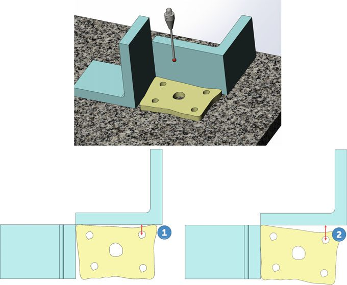
Fig. 1.5 Without any indication of the datums, the control of the position of the holes is not univocal or repeatable (measurements 1 and 2 give different results, according to the support system of the part used during the verification)
Inconveniencies of this type are more common than one might think, and they may lead to negative effects on the cost and times necessary for the construction of a component.
In short, the technical product documentation of a product without functional geometric tolerances and without any indication of datums is generally incomplete,
and therefore not unambiguously interpretable. Such an incomplete, ambiguous tolerancing of components on engineering drawings leads not only to increased production and inspection costs but also to an incalculable liability risk in the case of legal disputes.
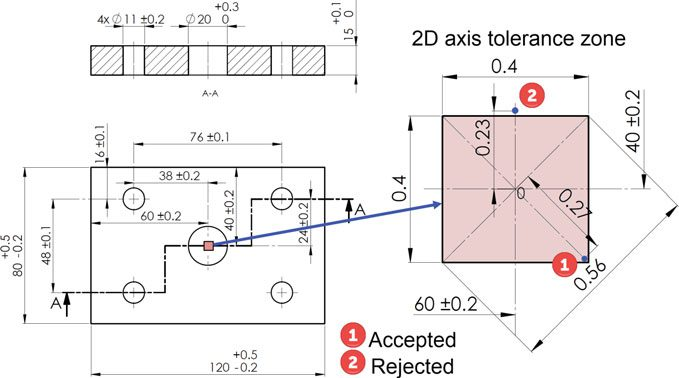
Fig. 1.6 Starting from the theoretical position (point 0), the limit positions allowed for the axis may be larger or smaller, depending on the radial directions. The axis position of the hole at point 1 is accepted during the control, but if it occurs at point 2, the workpiece is discarded. But which of the two holes is closest to the ideal position?
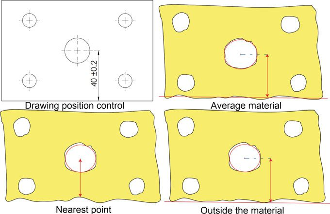
Fig. 1.7 The control of the position of a hole may be achieved by resorting to of the use of ideal circles and surfaces (known as associated geometry in the ISO system). The three verification methodologies shown in the figures could furnish contrasting results
Reference
1. KrulikowskiA(1997) Fundamentals ofGD&Tself-studyworkbook, 2nd edn. Effective Training Inc.